Technical Data - AC & DC Motor

1. Definition of Motor
Motor is a machine to get a driving force for
rotation or straight movement by converting the electrical energy into
mechanical energy and the light-weighted motor which enables to select
the model suitable for the load, has less noise and vibration as well as
no exhaust pollution.
2. Features of DKM Motors
DKM AC geared motor was developed first in Korea in
1987 and has been used in a good reputation throughout the whole areas
of domestic/overseas industry up to know. Our AC geared motor is proud
of various and wide range of specification which satisfies various
electrical requirements from all over the world.
(1) Various and Abundant Models
- There are various and abundant models in frame size covering from □60/70/80/90mm such as Induction Motor, 2 Pole Motor, Reversible Motor, E.M. Brake Motor, Clutch & Brake Motor, Torque Motor and Speed Control Motor.
- For use voltage, we have various voltage specification covering all areas in the globe: 100V 50/60Hz(Japan), 200V 50/60Hz(Japan), 110V 60Hz(Taiwan), 220V 60Hz(Korea, Taiwan), 115V 60Hz(North America), 230V 50Hz(Europe, Oceania), 220V/240V 50Hz(South-East Asia)
(2) Low Noise and Low Vibration
- Due to the enhancement of quality standard such as places and conditions for motors to use, the low noise and low vibration are required.
- To satisfy theses conditions, we employed high precision of gear processing and skiving cutting method and we are making a rotor which is the root cause of vibration by verifying with balance machine for low noise and low vibration.
(3) Easy to Use
- Easy and safe to use as motor and gearhead are sold according to the requirements so that it can be designed and manufactured optimally.
- It is easy to drive to get a driving force by connecting capacitor to the commercial power available to be used anywhere and anytime. As capacitor is not needed for three phase power, it is available to get a driving force easily by connecting three phase power to the motor directly.
(4) Just-In-Time System
- Just-In-Time system is available in DKM Motor Co., Ltd. for the best delivery system. DKM realized user's satisfaction with the world best delivery system.
3. Types of Motor
(1) Classification by Power
1) AC motor: A motor operated by AC power. For example, inductive motor, synchronous motor, AC commutator motor etc.
① Single Phase Motor
- Single phase power is composed of one phase as commercial power for home.
- As power itself does not make motor rotate, capacitor is connected to auxiliary coil to start.
② Three Phase Motor
- Three phase motor stands for electrical power and it is consisted of three electrical sources with a phase of 120° in voltage.
- Connect the power to motor to start and the rotor will start to run easily.
- The efficiency of motor is high and the starting torque is relatively big.
2) DC motor: A motor which rotates by supplying the
direct current to the armature. The torque generated by placing the
coil between magnetic poles N and S and applying the current to this
coil rotates the motor. Whenever this coil passes the neutral shaft, it
turns the direction of current reversely and rotates continuously
(2) Classification by Function
1) Motor with Constant Speed
⑴ Induction Motor : An induction motor which is a
type of AC motor where power is supplied to the rotor by means of
electromagnetic induction. These motors are widely used in industrial
drives, particularly polyphase induction motors, because they are rugged
and have no brushes. Their speed is determined by the frequency of the
suppply current, so they are most widely used in constant-speed
applications, although variable speed versions, using variable frequency
drives are becoming more common.
⑵ Reversible Motor: A kind of induction motor and a motor having the same characteristic in any direction such as left turn or right turn. In principle, it is same as induction motor but there is no relation of main coil and auxiliary coil like general induction motor in order to stand frequent normal/reverse rotation and get a big starting torque.
⑵ Reversible Motor: A kind of induction motor and a motor having the same characteristic in any direction such as left turn or right turn. In principle, it is same as induction motor but there is no relation of main coil and auxiliary coil like general induction motor in order to stand frequent normal/reverse rotation and get a big starting torque.
2) Electromagnetic Brake Motor
It is a motor embedded with fail-safe
electromagnetic brake. Perfect braking enables to get a staying power.
Brake runs only when the power is shutdown, so this is suitable as a
brake for safe use.
※ DKM havs 'A Type' electronic brake motor which runs when the power is applied. (Customized specification)
※ DKM havs 'A Type' electronic brake motor which runs when the power is applied. (Customized specification)
3) Clutch & Brake Motor
DKM Clutch & Brake motor is equipped with
Clutch & Brake mechanism available to be used with gearhead. As the
continuously rotating induction motor and Clutch & Brake are
combined, this can be used for frequent start/stop, position control,
index operation and relative value feeding operation etc.
4) Torque Motor
DKM torque motor has big starting torque and
sloping characteristics. It runs safely over the whole area of rotation
speed-torque characteristic. (Torque is highest at zero speed and
decreases steadily with increasing speed) With these characteristics,
this can be used for more application as a winding or tension motor.
5) Speed Control Motor
User can easily set and adjust the motor speed.
There are three kinds of speed controller for AC speed motors. Select
the best system depending upon your application.
4. Structure of AC Motor
① Flange Bracket
Die-cast aluminum bracket is press-fitted into the motor case. The
flange and the housing are a single body type which plays an important
part to attach the motor alone or combine the gearhead.
② Stator
This is comprised of a stator core made from laminated silicon/steel
plates, a polyester-coated copper coil and insulation film. The roles
are to generate magnetic field, form the rotation and run the rotor.
③ Motor Case
Die-cast aluminum with a machined finish inside
④ Rotor
It is comprised of laminated silicon/steel plates with die-cast
aluminum. Rotor plays the part to change the electric energy to
mechanical energy and transfer it to outside through shaft.
⑤ Output Shaft
There are round type shaft, D-cut type shaft, key type shaft which are
for using by motor itself and gear type shaft (pinion shaft) which is
for attaching gearhead. It is made by S45C with a machined finish.
⑥ Ball Bearing
It ensures that the rotor remains at the right position for the reliability and fast rotational motion.
⑦ Lead Wire
Lead wires with heat-resistant polyethylene coating
⑧ Painting
Backed finish of acrylic resin and melamine resin with beautiful look
5. Temperature Rise of AC Motor
(1) Temperature Rise
In operation of motor, the loss inside of motor is changed to heat causing the motor’s temperature to rise.
- Induction motor (for continuous duty) reaches the saturation point of temperature rise in about two or three hours of operation and temperature stabilizes.
- Reversible motor (30 minutes rating) reaches their limit of temperature rise in about 30 minutes of operation. If operation continues as it is, the temperature will increase further.
(2) Measuring Temperature Rise
DKM uses the following methods for temperature measurement and for the determination of a motor’s allowable temperature rise.
- Thermometer Method: The temperature rise at which the temperature rise becomes saturated during motor operation is measured by using a thermometer or thermocouple installed in the center of the motor case. The temperature rise is the difference between the ambient temperature and measured temperature during motor operation.
- Resistance Method: This is the way of measuring the winding temperature according to the change in resistance value. The motor’s winding resistance and ambient temperature is measured by using a resistance meter and thermostat.
(3) Overheating Protection Devices
In case of that a running motor locks due to
overload or the input current increases due to any reason or ambient
temperature increases suddenly, the motor’s temperature rises abruptly.
If this state continues, the insulation performance may deteriorate and,
in extreme cases, it may cause a fire. To avoid this case, DKM employs
the following overheating protection devices.
- Thermal Protector (TP)
DKM installs the thermal protector for overheating protection of the motor. The TP employs a bimetal contact with pure silver used in the contacts. Pure silver has the lowest electrical resistance of all materials and has thermal conductivity second only to copper. (Operating Temperature: Open 120℃±5℃ / Close 90℃±5℃)
- Impedance Protection
Impedance-protected motor has higher impedance in the motor windings so although the motor locks, the increase in input current is minimized and temperature will not rise.
(4) Insulation Class
DKM Motor’s insulation class is B class. Insulation
class is according to heat-resistance class. According to JIS
C4003(IEC60085), it is defined as below. It is also available to use
other materials for some particular insulation class according to
operating conditions or user's request. (Customized specification)
| Insulation class | Max. permissible Temp. |
| Y | 90℃ |
| A | 105℃ |
| E | 120℃ |
| B | 130℃ |
| F | 155℃ |
| H | 180℃ |
(5) Fan
It is available to attach two kinds of fan to the DKM's motor; ‘General Fan (F type)’ and ‘Powerful Fan(F2 type)’.
General fan is attached to motor shaft rotating in same speed as that of motor shaft.
(1800rpm in 60Hz, 1500rpm in 50Hz)
Powerful fan makes powerful cooling performance rotating in high speed regardless of motor shaft speed.
(3200rpm in 60Hz. Temperature reducing over 10℃ is available comparing general fan)
DKM employs general fan to the motors with continuous speed and employs powerful fan by customers’ special order to the continuous speed’s motor.
But in case of speed control motor in which speed control is needed, powerful fan is employed basically because there is little cooling effect in low speed if general fan is used.
6. Sizing of Motor
For the calculation way of load torque, refer to
below for the reference. According to this, needed motor sizing is
decided. Be advised that basic calculation way is referred below. So in
real sizing consider the acceleration time in start, needed power,
safety index in design and manufacturing and the influence by voltage
fluctuation and select motor considering.
7. Technical References of AC Motor
(1) Induction Motor Technical Reference
1) The Relation between Speed and Torque
|
In a condition of constant power voltage, the relation between speed and torque is like right figure. Under the condition of no-load, the number of rotation is roughly same as the number of synchronous rotation. But if the load increases, the number of rotation decreases and approaches to the speed(rpm) indicated by the point P where the torque Tp horizontally meets the load curve. When the load further increases and reaches the point M, the motor stops at the point R because the motor no longer generates further torque. Therefore, the leg R-M is referred to as an unstable zone and the leg O-M is a stable zone for operation. |
 |
2) Features of Voltage and Capacitor
Generally the torque of induction motor changes
proportionate to twice the voltage and it also changes according the
capacity of the capacitor.
If the capacity of the capacitor increases, the starting torque and rated torque will increase. But if the capacity increases by over 2 times, the rated torque decreases and starting torque do not increase.
When the induction motor is short on torque, it is possible to increase the torque by increasing the voltage or the capacity of the capacitor to continue the operation. But please be informed that in this case the loss input of the motor increases and the temperature rises rapidly.
However, if the motor must be run with insufficient torque, take measures to let the motor release heat as much as possible by installing separate fan as an example and operate the motor while keeping the temperature of the motor's housing below 90℃.
(2) Reversible Motor Technical Reference
1) Brake Mechanism of the Reversible Motor
A reversible motor employed a simple and built-in brake mechanism for the following purposes:
ⓐ To improve the frequent and instant reversing function by applying a friction load.
ⓑ To reduce overrun The coil spring applies constant pressure so that the ceramic (brake block) slides toward the brake plate. This mechanism provides some degree of holding brake force, but there is limit in the force due to the mechanism’s structure. The brake force is approximately 10% of the motor’s output. |
 |
|
2) Speed-Torque Characteristics
The reversible motor is a single-phase induction
motor of capacitor run type which has the same characteristics as an
induction motor.
The reversible motor has a higher starting torque than an induction motor in order to improve the instant reversing characteristics.
3) Operation Time and Temperature Rise
The rating time of reversible motor is 30 minutes.
But when the motor is operated intermittently for a short period of
time, the operation time may vary depending on the operating conditions.
The intermittent operation for a short period of time will cause a
considerable flow of electric current in starting or reversing causing
greater heat generation. But the motor's temperature rise can be
controlled by keeping the motor at rest without using for a longer time
by enhancing its natural cooling capability. Generally if the
temperature of motor case remains below 90℃ constantly, the continuous
operation is possible under unchanged condition considering insulation
class of coil winding. But the life time of bearing grease will be much
longer, the lower temperature.
|
(3) Electromagnetic Brake Motor Technical Reference
1) Power Off Activated Type Electromagnetic Brake
AC electromagnetic brake is employed in
electromagnetic brake motors. When the power is turned off, the brake is
activated and the motor stops instantaneously and holds the load. The
electromagnetic brake has holding power in power-off, so it is optimal
for emergency brakes and vertical load applications.
2) Operation
- There is 2-3 times of overrun rotation at the time the power is turned off as individual motor. (Induction motor: 30~40 times overrun, Reversible motor: 5~6 times overrun)
- The frequent and instantaneous directional changes are possible. By a simple control, it is possible to make 6 stops per minute with more than 3 seconds of stoppage. Roughly the operating cycle is 50cylces per minute or less. (Note: This value is based merely on brake response. And this value is maximum, so it may not be possible to repeat braking operation at this frequency. Please make the treatment so that the surface of the motor case remains below 90℃.)
- The motor and the brake use the same power source. (For example, if motor voltage is 110V, that of brake is 110V.)
3) Structure
| An electromagnetic brake motor is equipped with a power-off activated type electromagnetic brake. As shown in the figure, when voltage is applied to the magnet coil, the armature is attracted to the electromagnet against the force of the spring, thereby releasing the brake and allowing the motor shaft to rotate freely. When no voltage is aaplied, the spring works to press the armature onto the brake hub and hold the motor's shaft in place, thereby actuating the brake. |  |
|
(4) Clutch & Brake Motor Technical Reference
1) Clutch & Brake Mechanism
An internal clutch & brake mechanism for use
with a gearhead is employed in clutch & brake motor. By the
combination of a constantly rotating induction motor and a clutch and
brake unit, the function of frequent start/stop, positioning, indexing,
jogging and incremental feeding are available.
DKM's clutch & brake motor is designed for the quicker response time and higher torque to move the load. To meet high-frequency, starting and stopping applications, DKM uses induction motor for its continuous duty rating. So clutch & brake motor is not suitable for frequent bi-directional starting and stopping motion but suitable for unidirectional movement.
2) Structure and Mechanism
|
 |
|
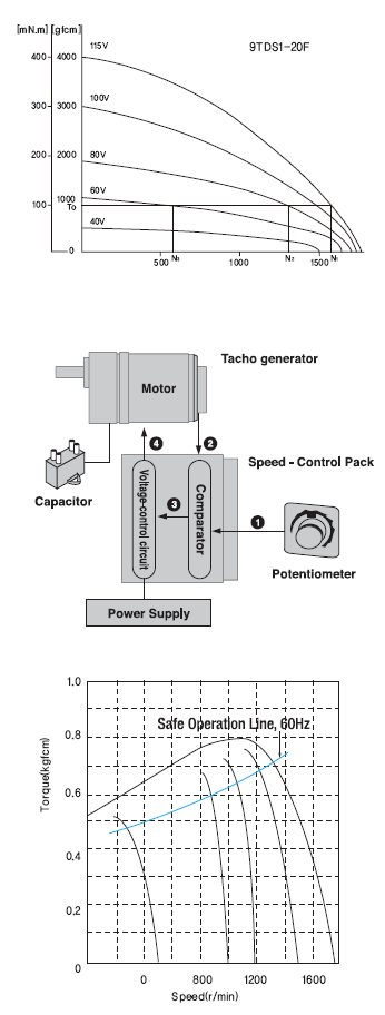
(5) Torque Motor Technical Reference
The torque of torque motor is approximately in proportion to the square of the voltage.
When the voltage supplied to the motor is changed, speed- torque curves with a sloping characteristics (torque is
highest at zero speed and decreases steadily as speed increases) will be corresponding voltage.
If the voltage is changed to 115VAC, 80VAC and 60VAC while the load torque is T0, the motor rotates at the speeds N1, N2 and N3 respectively. That is to say, the speed can be changed easily by varying the voltage. In choosing a torque motor, first determine the required torque and speed and then select a motor using the speed-torque characteristics curves to determine whether the motors should be operated under continuous duty or limited duty. In using motor under locked rotor conditions, only the torque factor is considered.
(6) Speed Control Motor Technical Reference
1) Speed Control Methods of Speed Control Systems
① By a potentiometer, the speed setting voltage is supplied.
② The speed of the motor is sensed and the speed signal voltage is supplied. ③ The difference between the speed setting voltage and speed signal voltage is supplied. ④ A voltage determined by the output from the capacitor is supplied to the motor so that it will reach the set speed.
2) Speed-Torque Characteristics and Safe Operation Line
The speed-torque characteristics line of all AC speed control motors is shown in the right figure.
Each set speed changes slightly according to the change in load torque.
Input power to the speed control motor depends on the load and speed. The greater the load, and the lower the speed, the greater an increase in motor temperature. In the speed-torque characteristics graph, the line is referred to as the safe operation line, while the area below the line is called the continuous operation area. The safe operation line, measured according to motor temperature, indicates its operational limit for continuous usage with the temperature. Whether the motor can be operated at a specific torque and speed is determined by measuring the temperature of the motor case. In general, if the temperature of the motor case is below 90℃, continuous operation is possible considering the insulation class of motor coil winding. But the motor life could be extended with lower motor temperature. So it is recommended that keep the motor temperature low. DKM has two kinds of cooling fan; General Fan (F Type) and Powerful Fan (F2 Type). General fan is attached in motor shaft and its speed depends on the motor shaft speed. So in slow speed of motor, there is very weak cooling effect. In the application where motor speed should be changed from low speed (below 1000rpm) to high speed like speed control motor, powerful fan is needed so that cooling effect keep constantly regardless of the motor speed. In case of speed control motor DKM is employg powerful fan (F2 Type) into them basically. In special application or by user's request general fan can be employed in speed control motor. |
 |
(7) DC Motor Technical Reference
1) Features of DC Motor
- DC motor has a big starting torque and excellent mobility and when comparing with the same sized AC motor, the output is big and the efficiency is high.
- It is easy to control the speed and change the normal/reverse rotation.
- Comparing to AC motor, it is available to manufacture low voltage motor which can be applied to portable machine which uses various spec., especially battery power (12V, 24V).
- Due to the wear of brush, there is a limit in the service life.
- Due to brush and commutator, noise generates when starting.
- DSD Speed Controller enables to adjust the speed easily. (Available to connect to DC 90V motor)
2) Current, Torque and Speed(r/min)
When the voltage of power supply is fixed, D.C.
magnet motor shows the characteristic in the relationship between
torque, speed and current as below.
The relationship is almost linear and the speed decreases, and current increases conversely when increasing the torque to the output shaft motor.
It is same until the output shaft of motor is done a stall, when ignored heat generation in the motor. (It is possible to control the torque by controlling the current.)
3) Rating Time
According to increase of current (and torque), heat
generation in the motor increases. Generally, when the temperature of
component parts in the motor is below than allowable temperature after
it was saturated, it is possible to keep continuous operation.
When it was not saturated in the allowable temperature, the time to exceed the temperature is rating time of motor and it is short-time rating specification. According to size and the specification, each motor model has different current(torque) value to be possible continuous operation.
When it was not saturated in the allowable temperature, the time to exceed the temperature is rating time of motor and it is short-time rating specification. According to size and the specification, each motor model has different current(torque) value to be possible continuous operation.
4) Performance of DC Motor in case of Voltage Change at Power Supply
| D.C. magnet motor can change speed
by changing power supply voltage. The relationship between torque(t),
Speed(N) and current(I) of motor when the voltage is half(1/2) is shown
as below. As the above figure, in the relationship between current and speed when power supply voltage was changed to half(1/2), ideal no-load speed "Nt" becomes "Nt/2" and it falls parallel to the performance of rated voltage. The relationship between current and torque is same as the rated voltage, but the stall current "ts" falls accordingly as the stall current "Is" becomes "Is/2". ① No-load speed when voltage is half(1/2) ② I-N characteristic at rated voltage ③ I-N characteristic when the voltage is half(1/2) ④ Stall torque when the voltage is half(1/2) ▶ Nt : Ideal no-load speed when current is zero. (the point extended the diagram of speed to zoo current.) |
 |
5) Input, Output and Efficiency of DC Motor
The input, output and efficiency can be calculated with the next formula.
Tidak ada komentar:
Posting Komentar